Hello OCRA and Tabletop community,
In this blog post I want to share our console power supply for the OCRA Tabletop MRI System.
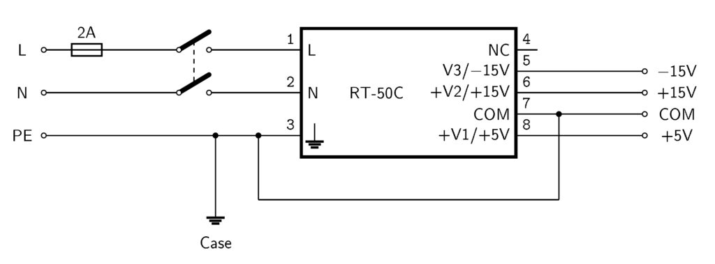
The console is driven by a Mean Well RT-50C switching mode power supply with a universal 110/230V AC input and +15V, -15 and +5V DC outputs. To connect the power supply to house power a standard IEC connector can be used. A 2A fuse on the input (L line) is needed to protect the power supply and the L and N line are both switched with a 2pol On/Off switch. The switching mode power supply is connected in the PELV configuration to pull the otherwise lifted outputs to a common ground (GND). The schematic is shown in image1.
The outputs of the switching mode power supply connect to the inputs (J1) Powersupply PCB. The Red Pitaya can be driven by the USB type A connector (J8). The Red Pitaya is the required minimum load for the +5V output of the RT-50C. Not connecting the Red Pitaya can lead to instable voltages on the +15V/-15V outputs. A dummy load on the 5V output can be used in this case.
For the other paths the voltages are filtered with 6th order low pass filters made of ferrites and capacitors. They use the same components as the OCRA1 board. Each path (+15V, -15V and +5V) is rated for 500mA. There are additional Voltages created by linear regulators. 3.3V is necessary for the OCRA1 board. 12V is used to drive the OCRA Tabletop RFPA and 2nd stage low noise amplifier. 10V is optional and can be used for other standard MR preamps like from Siemens or WanTcom. Each linear regulator is rated for 500mA peak. 10pin terminal blocks provide the output connections for all voltages.
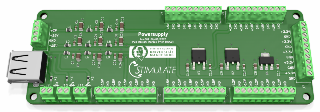
Image2: The OCRA console power supply PCB.
There are connections for status LEDs of the input voltage lines. J9 for +5V, J10 for +15V and J11 for -15V. R1, R2 and R3 are the LED series resistors for each line. The value depends on the LED you use and need to be calculated.
R = ( U – U_LED ) / I_LED
The PCB .gerber files, schematic, material list and fabrication plan are in the .zip file:
https://cloud.ovgu.de/s/nrK65GW2EJB4XwN
When downloading the files, you declare to cite us as creator of the OCRA console power supply when using in your projects or publications (Marcus Prier, Forschungscampus STIMULATE, Otto-von-Guericke University Magdeburg). You are not allowed to remove logos or references.
Disclaimer
As the switching mode power supply input is on house power: Only professionals are allowed to work with house power. Working with house power is on your own risk! Be careful.
If you have questions about the OCRA console power supply or interest in preassembled PCBs, Tabletop and OCRA components or even a whole OCRA Tabletop MRI System contact me via marcus.prier@ovgu.de.
Best Regards
Marcus
0 thoughts on “Power supply of the OCRA console”