Hello OCRA and Tabletop community,
In this blog I will guide you on how to test the RF functionality of the OCRA Tabletop MRI System. We will test the functionality for receiving RF spin signals (RX) and transmiting RF pulses (TX).
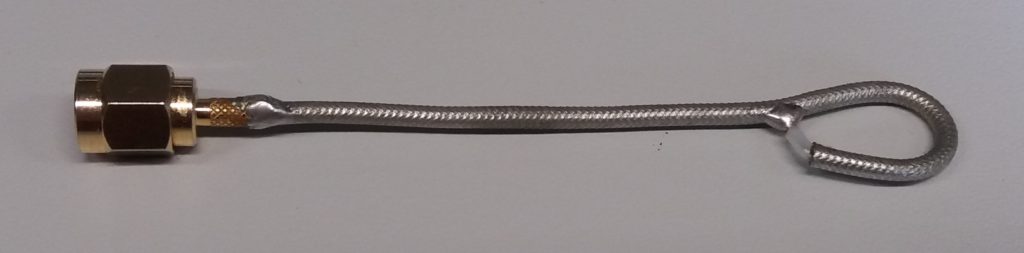
For the tests you need a pickup loop coil. The coil can be build out of a piece of thin semi-rigid coaxial wire and a small SMA connector. The coil needs to fit in the Tabletop bore and needs a diameter of about 10 to 15mm. A recommended design is shown in image1.
Testing the Tabletop receive functionality
To test the receive functionality of the system the idea is to send a small defined RF signal with Larmor frequency to the Tabletop RF coil. To do this the pickup loop coil needs to be connected to a function generator and placed inside the Tabletop bore. The Tabletop Magnet RF system needs to be connected to the OCRA console. The complete setup is shown in image2.
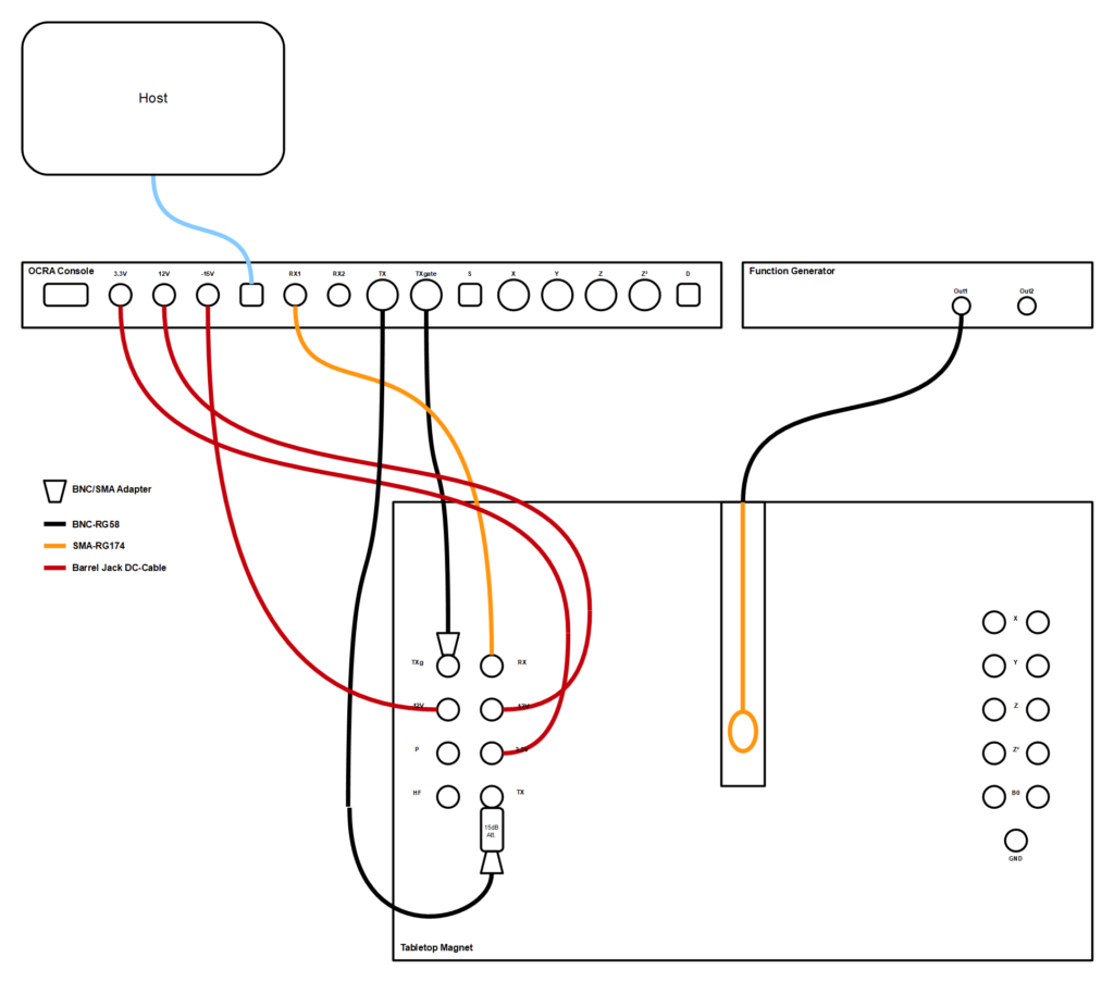
Function generator setup:
- Sine wave
- Frequency: Larmor frequency, here 11.3MHz
- Power level: 10mV RMS
OCRA software setup:
- Spectroscopy
- Sequence: Spin Echo
- Center frequency: Same value as the function generator (11.3MHz)
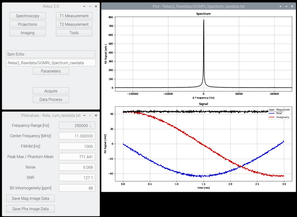
When acquiring and measuring the signal a sharp peak in the frequency domain should appear. An expected result is shown in image3.
Testing the Tabletop transmit functionality
To test the transmit functionality of the system the idea is to send a RF pulse with the system and sense it with the pickup loop coil and an oscilloscope. To do this the TX gate output of the OCRA console needs to be split with a BNC-T-adapter and connected to the first channel of the oscilloscope. This allows easy RF pulse timed triggering. The pickup loop coil needs to be connected to the second channel of the oscilloscope and is placed in in the Tabletop bore. The Tabletop Magnet RF system needs to be connected to the OCRA console. The complete setup is shown in image4.
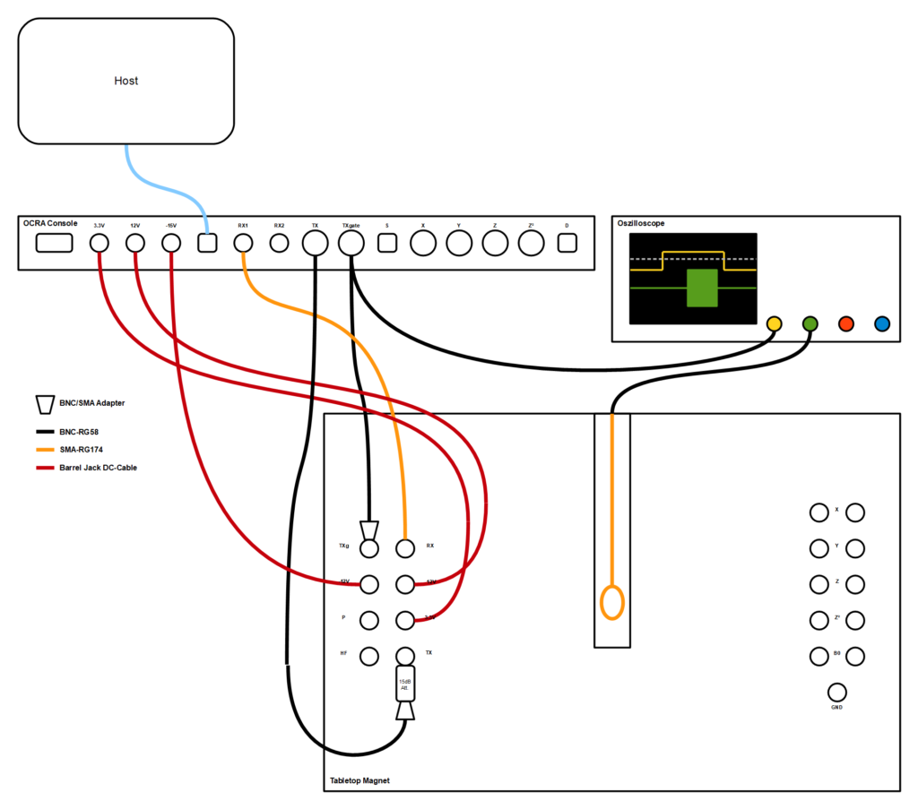
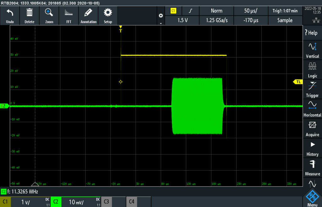
Oscilloscope setup:
- Time resolution: 50us/Div
- First channel: 1V/Div
- Second channel: 10mV/Div
- Trigger:
- On first channel
- Rising edge
- About 1.5V
- “Single” or better “Normal” mode.
OCRA software setup:
- Spectroscopy
- Sequence: Spin Echo
- Center frequency: Larmor frequency, here 11.3MHz
- RF Attenuation: about -15dB
When acquiring and measuring the signal the TXgate and a relative clean RF pulse should be shown on the oscilloscope. An expected result is shown in image5.
With a working RF system it should be possible to measure MR signals. There are more technical reasons for a missing RF spin signal. For example a bad static magnetic field (B0) or wrong RF pulse power. This i will explain in a future blog post.
I hope this blog helps to understand the OCRA Tabletop RF system. If you have questions about the OCRA Tabletop RF system or interest in preassembled PCBs, Tabletop- and OCRA components or even a whole OCRA Tabletop MRI System contact me via marcus.prier@ovgu.de.
Best regards,
Marcus
0 thoughts on “Testing the transmit and receive functionality of the OCRA Tabletop MRI System”