Hello OCRA, Tabletop and OSI² community,
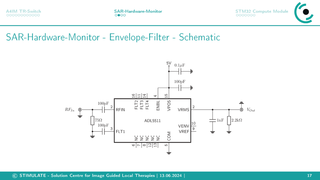
In this blog post I want to share our SAR Power Monitor µC Interface for the OSI² 2MHz Halbach MRI as part of the A4IM project. The PCB uses the ADL5511 RF-to-RMS IC to convert the applied RF power to a envelope RMS voltage. This voltage gets sampled with a stepping of 10µs by the micro controller STM32L476RGT compute module.

The SAR Power Monitor µC Interface has two RF inputs.
In 1 (Forward power):
- Peak detection
- 10s running average SAR limit (10ms check interval)
- 6min running average SAR limit (10s check interval)
In 2 (Reflected power)
- Peak detection (programmable percentage of forward power, default 20%)
The SAR Power Monitor gets integrated in the RF chain of the OSI² Halbach MRI with a dual directional coupler (f.e. Mini-Circuits ZFBDC20-61HP+) on the RFPA output. When a limit is exceeded the SAR Power Monitor will switch off the RFPA blanking signal and so the RFPA. The blanking signal is switched by a solid-state relais (Finder 34.81.7.005.9024), which can handle external 1.5V-33V blanking signals.
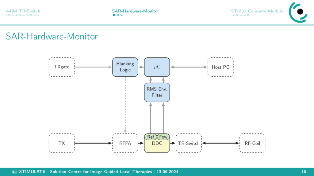
The blanking is secured by a blanking logic circuit on the PCB, that contains a watch-dog IC to monitor the functionality of the µ-Controller, and a TLC555 timer IC. The TLC555 is used as an RS-flip-flop and ensures that the blanking signal stays off when an SAR error occurs (Out signal of the µC) or the µC is not in sampling mode. Only a dedicated Reset signal can to reset the blanking output. As the solid state relais is a power switch an 50Ohm terminating resistor may be required at the blanking input of the RFPA.
Like the A4IM OSI² TR-Switch the SAR Power Monitor has a EMI housing.
The matching SAR Power Monitor µC software will be shared in future.
The PCB .gerber files, schematic, material list and fabrication plan are in the .zip file:
https://cloud.ovgu.de/s/wMwiq5zaRJ6yXYa
CAD files, vector graphics material lists are in the following .zip file:
https://cloud.ovgu.de/s/f34NM6btnqFXwXS
When downloading the files, you declare to cite us as creator of the A4IM OSI² SAR Power Monitor when using in your projects or publications (Marcus Prier, Forschungscampus STIMULATE, Otto-von-Guericke University Magdeburg). You are not allowed to remove logos or references.
If you have questions about the A4IM OSI² SAR Power Monitor or interest in preassembled PCBs, Tabletop and OCRA components or even a whole OCRA Tabletop MRI System contact me via marcus.prier@ovgu.de.
Best regards,
Marcus
0 thoughts on “A4IM OSI² SAR Power Monitor µC Interface PCB”