Hello OCRA, Tabletop and OSI² community,
In this blog post I want to share my Transmit-Receive (TR) switch design for the OSI² 2MHz Halbach MRI as part of the A4IM project. The A4IM OSI² TR-Switch is based on my OCRA Tabletop MRI System TR-Switch. The schematic is basically the same and only a few components are replaced to handle the higher power RFPA of the Halbach MRI System. The A4IM OSI² TR-Switch can be directly controlled by the OCRA console with OCRA / Relax2.0.
Specifications:
- For up about 2000W RF peak power
- Tuneable from about 1.8MHz up to about 2.2MHz
- Extra TR-switch for RFPA noise blanking
- Powered by 3.3V, 12V (12V to 16V) and optional -15V (0 to -16V)
- Controlled with a LVTTL TXgate
- Integrated 1st stage low noise amplifier (bypass able)
- Semi-active design with PIN-driver
- Optional reverse bias
- External 50Ohm noise blanking dump resistor
The detailed explanation of the OCRA Tabletop MRI System TR-Switch can be found here.
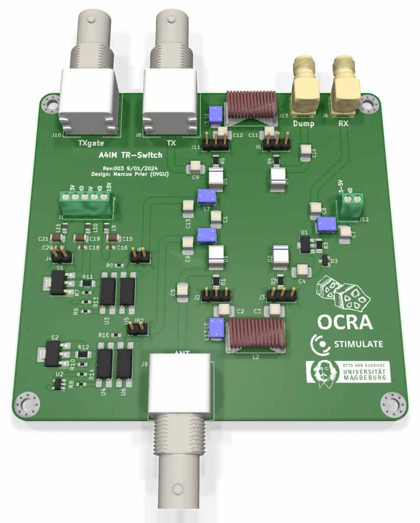
PCB assembly
For reference see the assembly instructions for the OCRA Tabletop MRI System TR-Switch.
Recommended RF components for 2.0MHz tuning:
- RF-chokes: Coilcraft 1812CS 33µH
- Pi element fixed inductor: Coilcraft 1812CS 3.9µH
- Pi element air coil inductor: Coilcraft 2929SQ 390nH
- Pi element capacitors: Passive Plus 1111C 1.5nF
When measuring the PIN driver voltages be aware that the header and jumper labels differ between the OCRA Tabletop MRI System TR-Switch and the A4IM OSI² TR-Switch. The first stage LNA is bypass able via the 0Ohm resistor R3.
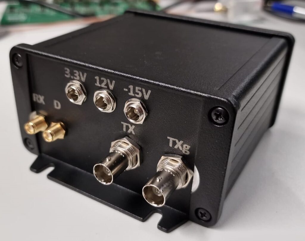
Housing assembly
A EMI shielded housing based on a Hammond Manufacturing 1457N1201EBK case can be build. I provide a CAD model that can be used for CNC milling and vector graphics for laser engraving. The vector graphics are scaled up by a factor 100 to avoid small detail artefacts, like corners of the font. The case is available with and without mounting flanges.
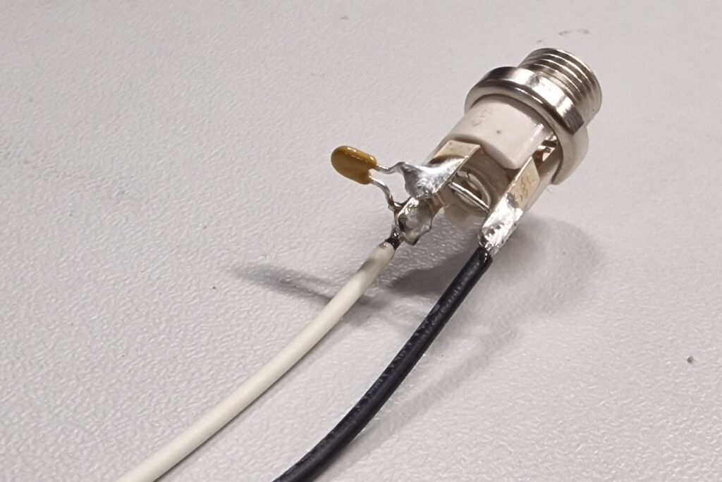
The cabling is very simple and a small schematic is given. For noise reduction on the DC power supply inputs a decoupling capacitor is soldered to the barrel jack pins between + and GND. The inner pin is + and the outer sleeve is GND.
External 50Ohm noise blanking dump resistor
The dump resistor “catches” the noise of the RFPA in receive mode. When the RFPA has a blanking input and fast blanking (<10us) the residual noise in receive mode is very low. If the RFPA has no blanking or the blanking is to slow residual noise in receive mode is can be very high. Therefor the external dump resistor needs to be matched with the noise power of the RFPA.
It is possible to use small SMA 50Ohm terminating resistor (f.e. Amphenol RF 132360) or bigger block resistors (f.e. Pasternack PE6TR1003). Also short SMA extension cables (f.e. Amphenol RF 135101-01-12.00) can be used to connect the RF block resistors and place it separate from the TR-Switch housing.
The PCB .gerber files, schematic, material list and fabrication plan are in the .zip file:
https://cloud.ovgu.de/s/Nnem6ww3PSmE9kg
CAD files, vector graphics material lists are in the following .zip file:
https://cloud.ovgu.de/s/kP8Wobo9pNWAt6w
When downloading the files, you declare to cite us as creator of the A4IM OSI² TR-Switch when using in your projects or publications (Marcus Prier, Forschungscampus STIMULATE, Otto-von-Guericke University Magdeburg). You are not allowed to remove logos or references.
If you have questions about the A4IM OSI² TR-Switch or interest in preassembled A4IM OSI² PCBs and components, OCRA and Tabletop components, or even a whole OCRA Tabletop MRI System contact me via marcus.prier@ovgu.de.
Best Regards
Marcus
0 thoughts on “A4IM OSI² TR-Switch”